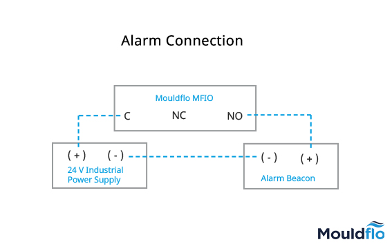
Alarm Connection with MFIO
Wire the ALARM ( C and NO) connections on the MFIO as per the attached
diagram.
For
example, in the attached picture, you can see a connection made from the MFIO
onto a 24 V alarm beacon.
Once
the alarm system is connected - on the Mouldflo software, in the manifold
configuration screen enable the appropriate channel(s) (with limits). When the
limits are breached, the Mouldflo software automatically triggers the relays
pertaining to the ALARM.
Related Articles
MFIO and Power Connections
For the MFIO: Red – V+ Black – 0V Blue – RS485_B White – RS485_A For Power: Please see the white markings on one section of the power cable ( it refers +V) and the pure black ( it refers -V)M12 Connector Information
Procedure to replace the SSD on the MFTR v2
Please find videos to replace the SSD : Part 1 - https://drive.google.com/file/d/1rI0JGeVT60gYGVaaR87WPZUhmmKS06St/view?usp=sharing Part 2 - https://drive.google.com/file/d/17W5uI_xmE-iN1wma4Yg0NZPAcjjHbu9K/view?usp=sharing Part 3 ...MFTR Software Upgrade Instructions
Please follow the below mentioned steps to upgrade the Test Rig software: Press Ctrl+Alt+T on the keyboard to launch the terminal. Please type the command “Killall -9 Mouldflo” and press “ENTER” on the keyboard. (The Test rig application should ...